- 您现在的位置:买卖IC网 > Sheet目录1993 > DS1077U-120+ (Maxim Integrated Products)IC ECONOSCILLATOR 120MHZ 8-USOP
DS1077
4 of 21
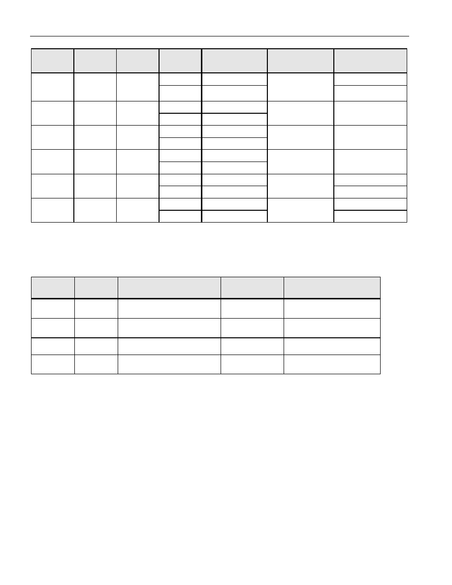
DEVICE MODE USING OUT0 Table 1
EN0
(BIT)
SEL0
(BIT)
PDN0
(BIT)
CTRL0
(PIN)
OUT0
(PIN)
CTRL0
FUNCTION
DEVICE
MODE
1
HI-Z
POWER-DOWN
0
HI-Z
POWER-
DOWN*
ACTIVE
1
MCLK/M
0
1
0
MCLK
MUX SELECT
ACTIVE
1
HI-Z
1
0
MCLK
OUTPUT
ENABLE
ACTIVE
1
HI-Z
1
0
MCLK/M
OUTPUT
ENABLE
ACTIVE**
1
HI-Z
POWER-DOWN
X
0
1
0
MCLK
POWER-
DOWN
ACTIVE
1
HI-Z
POWER-DOWN
X
1
0
MCLK/M
POWER-
DOWN
ACTIVE
*This mode is for applications where OUT0 is not used, but CTRL0 is used as a device shutdown.
**Default Condition
DEVICE MODE USING OUT1 Table 2
PDN1
(BIT)
CTRL1
(PIN)
CTRL1
FUNCTION
OUT1
DEVICE MODE
0
OUTPUT ENABLE
OUT CLK
ACTIVE**
0
1
OUTPUT ENABLE
HI-Z
ACTIVE**
1
0
POWER-DOWN
OUT CLK
ACTIVE
1
POWER-DOWN
HI-Z
POWER-DOWN
**Default Condition
NOTE:
Both CTRL0 and CTRL1 can be configured as power-downs. They are internally “OR” connected so that
either of the control pins can be used to provide a power-down function for the whole device, subject to
appropriate settings of the PDN0 and PDN1 register bits (see Table 3).
发布紧急采购,3分钟左右您将得到回复。
相关PDF资料
DS1081LE+
IC CLOCK MOD SS 8-TSSOP
DS1083LR-U+
IC CLOCK MOD SS 3.3V TSOT23-6
DS1100LZ-75+W
IC DELAY LINE 5TAP 75NS 8-SOIC
DS1100M-75+
IC DELAY LINE 5TAP 75NS 8-DIP
DS1110LE-125+
IC DELAY LINE 10TAP 14-TSSOP
DS1110S-80+
IC DELAY LINE 10TAP 16-SOIC
DS1123LE-100+
IC DELAY LINE 256TAP 16-TSSOP
DS1124U-25+T
IC DELAY LINE 256TAP 10-USOP
相关代理商/技术参数
DS1077U-120+T&R
制造商:Maxim Integrated Products 功能描述:ECONO-OSC 8P USOP 2-W 120MHZ T&R LF - Tape and Reel 制造商:Maxim Integrated Products 功能描述:IC ECONOSCILLATOR 120MHZ 8-USOP
DS1077U-120+T&R
功能描述:可编程振荡器 EconOscillator/Dvdr 120MHz 150mil 2-Wire RoHS:否 制造商:IDT 封装 / 箱体:5 mm x 7 mm x 1.5 mm 频率:15.476 MHz to 866.67, 975 MHz to 1300 MHz 频率稳定性:+/- 50 PPM 电源电压:3.63 V 负载电容:10 pF 端接类型:SMD/SMT 输出格式:LVPECL 最小工作温度:- 40 C 最大工作温度:+ 85 C 尺寸:7 mm W x 5 mm L x 1.5 mm H 封装:
DS1077U-125
功能描述:可编程振荡器 EconOscillator/Dvdr 125MHz 150mil 2-Wire RoHS:否 制造商:IDT 封装 / 箱体:5 mm x 7 mm x 1.5 mm 频率:15.476 MHz to 866.67, 975 MHz to 1300 MHz 频率稳定性:+/- 50 PPM 电源电压:3.63 V 负载电容:10 pF 端接类型:SMD/SMT 输出格式:LVPECL 最小工作温度:- 40 C 最大工作温度:+ 85 C 尺寸:7 mm W x 5 mm L x 1.5 mm H 封装:
DS1077U-125/T&R
功能描述:可编程振荡器 RoHS:否 制造商:IDT 封装 / 箱体:5 mm x 7 mm x 1.5 mm 频率:15.476 MHz to 866.67, 975 MHz to 1300 MHz 频率稳定性:+/- 50 PPM 电源电压:3.63 V 负载电容:10 pF 端接类型:SMD/SMT 输出格式:LVPECL 最小工作温度:- 40 C 最大工作温度:+ 85 C 尺寸:7 mm W x 5 mm L x 1.5 mm H 封装:
DS1077U-125+
功能描述:可编程振荡器 EconOscillator/Dvdr 125MHz 150mil 2-Wire RoHS:否 制造商:IDT 封装 / 箱体:5 mm x 7 mm x 1.5 mm 频率:15.476 MHz to 866.67, 975 MHz to 1300 MHz 频率稳定性:+/- 50 PPM 电源电压:3.63 V 负载电容:10 pF 端接类型:SMD/SMT 输出格式:LVPECL 最小工作温度:- 40 C 最大工作温度:+ 85 C 尺寸:7 mm W x 5 mm L x 1.5 mm H 封装:
DS1077U-125+T&R
制造商:Maxim Integrated Products 功能描述:ECONO-OSC 8P USOP 2-W 125HZ T&R LF - Tape and Reel 制造商:Maxim Integrated Products 功能描述:IC ECONOSCILLATOR 125MHZ 8-USOP 制造商:Maxim Integrated Products 功能描述:Programmable Oscillators EconOscillator/Dvdr 125MHz 150mil 2-Wire
DS1077U-125+T&R
功能描述:可编程振荡器 EconOscillator/Dvdr 125MHz 150mil 2-Wire RoHS:否 制造商:IDT 封装 / 箱体:5 mm x 7 mm x 1.5 mm 频率:15.476 MHz to 866.67, 975 MHz to 1300 MHz 频率稳定性:+/- 50 PPM 电源电压:3.63 V 负载电容:10 pF 端接类型:SMD/SMT 输出格式:LVPECL 最小工作温度:- 40 C 最大工作温度:+ 85 C 尺寸:7 mm W x 5 mm L x 1.5 mm H 封装:
DS1077U-133
功能描述:可编程振荡器 EconOscillator/Dvdr 133MHz 150mil 2-Wire RoHS:否 制造商:IDT 封装 / 箱体:5 mm x 7 mm x 1.5 mm 频率:15.476 MHz to 866.67, 975 MHz to 1300 MHz 频率稳定性:+/- 50 PPM 电源电压:3.63 V 负载电容:10 pF 端接类型:SMD/SMT 输出格式:LVPECL 最小工作温度:- 40 C 最大工作温度:+ 85 C 尺寸:7 mm W x 5 mm L x 1.5 mm H 封装: